05/13/2002 22:00 PDT

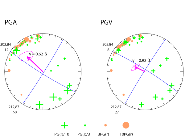
The residual PGAs and PGVs are plotted on whole stereonets. Symbols indicating the amplitude of the residual peak ground motions are plotted at the azimuths and vertical takeoff angles of the S-waves. Orange circles indicate amplified ground motions; green crosses indicate deamplified ground motions. Because we restrict the station distance, most takeoff angles are vertically upward, but the takeoff angles to the more distant stations can be slightly downward. The thick magenta lines show the rupture direction. The longer the line, the more horizontal the rupture direction. Upward rupture directions end in arrows; downward rupture directions end in stars. The thin magenta lines around the rupture directions enclose the 2σ uncertainty areas: these uncertainty areas can extend into both the upper and lower hemispheres. The blue lines show the nodal planes of the Berkeley Seismological Laboratory Moment Tensor, which are projected onto the upper or lower hemisphere, depending on the rupture direction. The sets of three numbers indicate the strike and dip of the nodal plane and the angle between the rupture direction and the nodal plane. If you are unfamiliar with nodal planes and stereoscopic projections, there is an excellent explanation titled Fault Plane Solutions. Remember that nodal planes are determined from P-wave first motions, while the directivity is determined from S-wave peak motions.
Aftershock sequence for this event
Map and cross-section
 Jump to Navigation